WS18 - Infantry man pack

Links on this page: Last time edited: 2012-12-22
Home WS18-WS48: a comparison
Textile covered cables - how-to-make-them Metering instruments (WS19 & WS62)
Restore of the cabinets - Under construction Tank coil up close


On May, 8, 2012 I obtained some parts of a WS18 Man pack: an apparently complete receiver and an incomplete transmitter. There was also a headphones / chest microphone combination with it, but this was not originally issued.
This will be a future restoring project, but I want to share the information and photo's of this set already.
I am rather happy to have this set in my collection, because it is alike the ones that have been used during the Battle of Arnhem (WS68), that took place about 10 km of my house. It was also the radio that was too weak to make connections between Oosterbeek (Hartenstein) and Groesbeek were HQ was established during that time. But that is quite another story.

Some data on the WS18:
- Built between end 1939 until end 1945. More than 76,000 were built by Pye Ltd and subcontractors. A lot of info can be found in the book "Wireless for the Warrior" by Louis Meulstee.
- Frequency range: 6 - 9 Mc, Power output: 0.25 Watt, effective range: R/T 5 miles, CW 10+ miles (using longest aerial available).

Here some photo's of the state it was on, on the moment of arrival: (click each photo to enlarge)


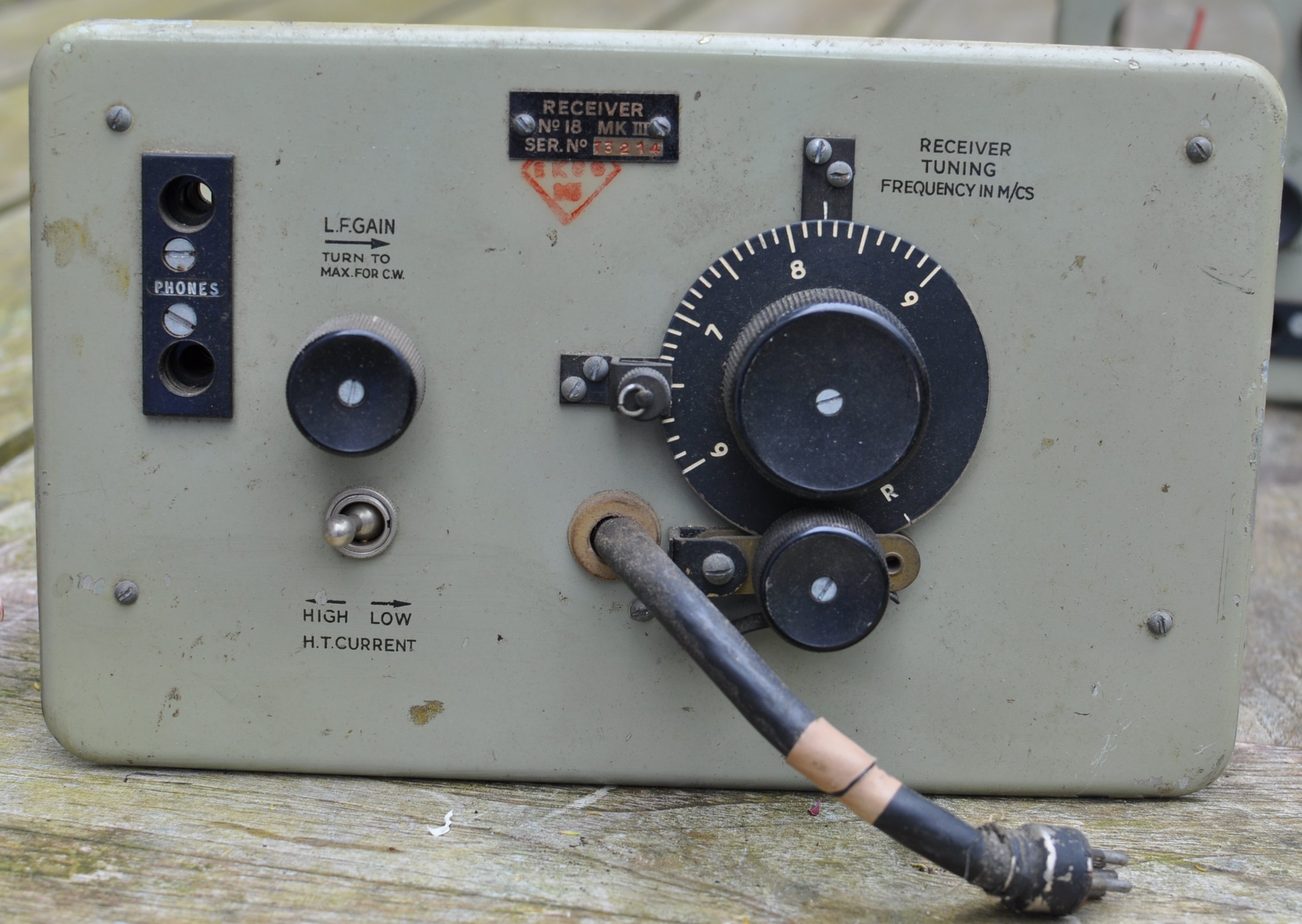
The Receiver part. Marked "RECEIVER No. 18 MK III SER. No. 73214"

The front looks very well. The interconnecting cable is made of rubber cable and uses a different 5 pin plug than what we are used to.

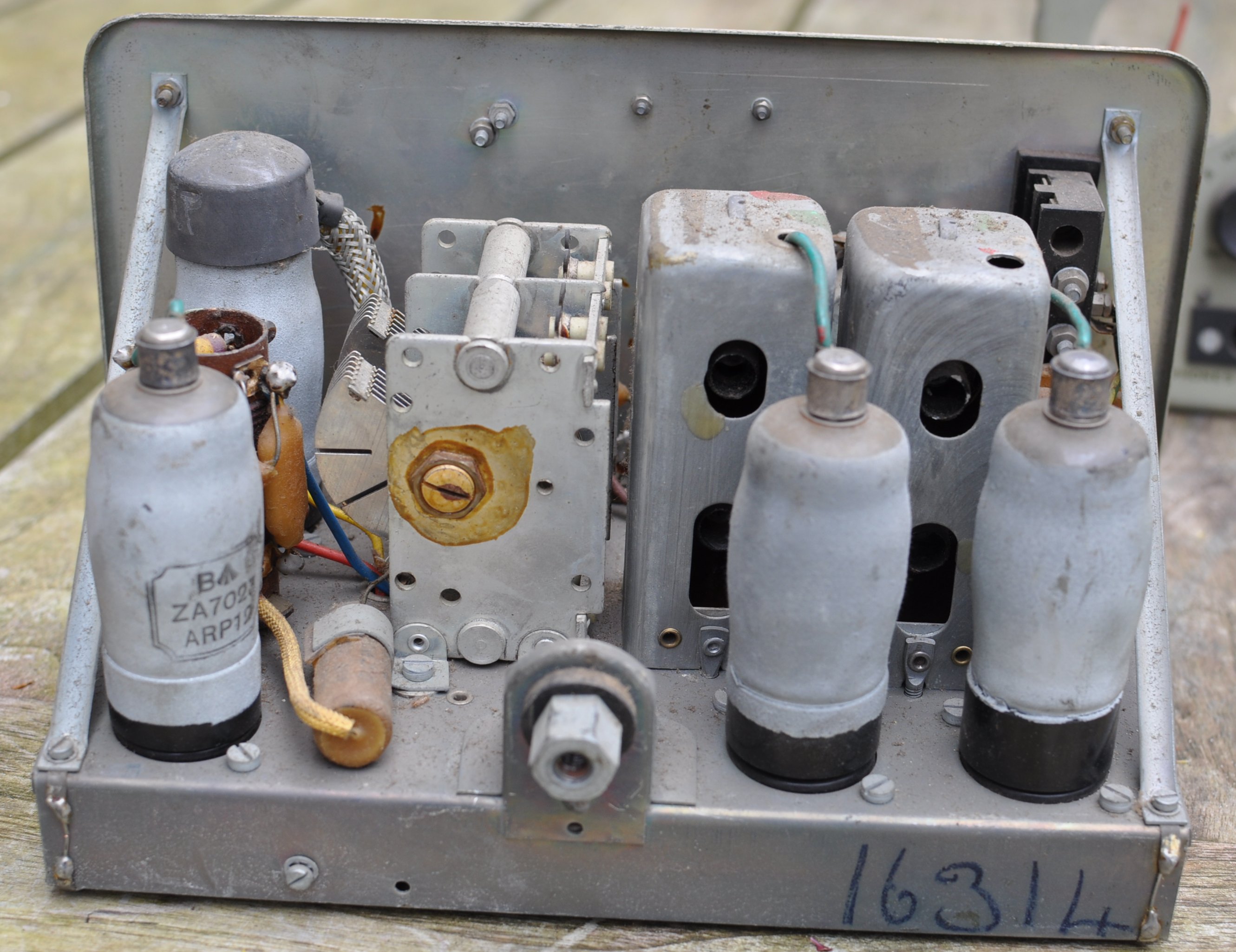
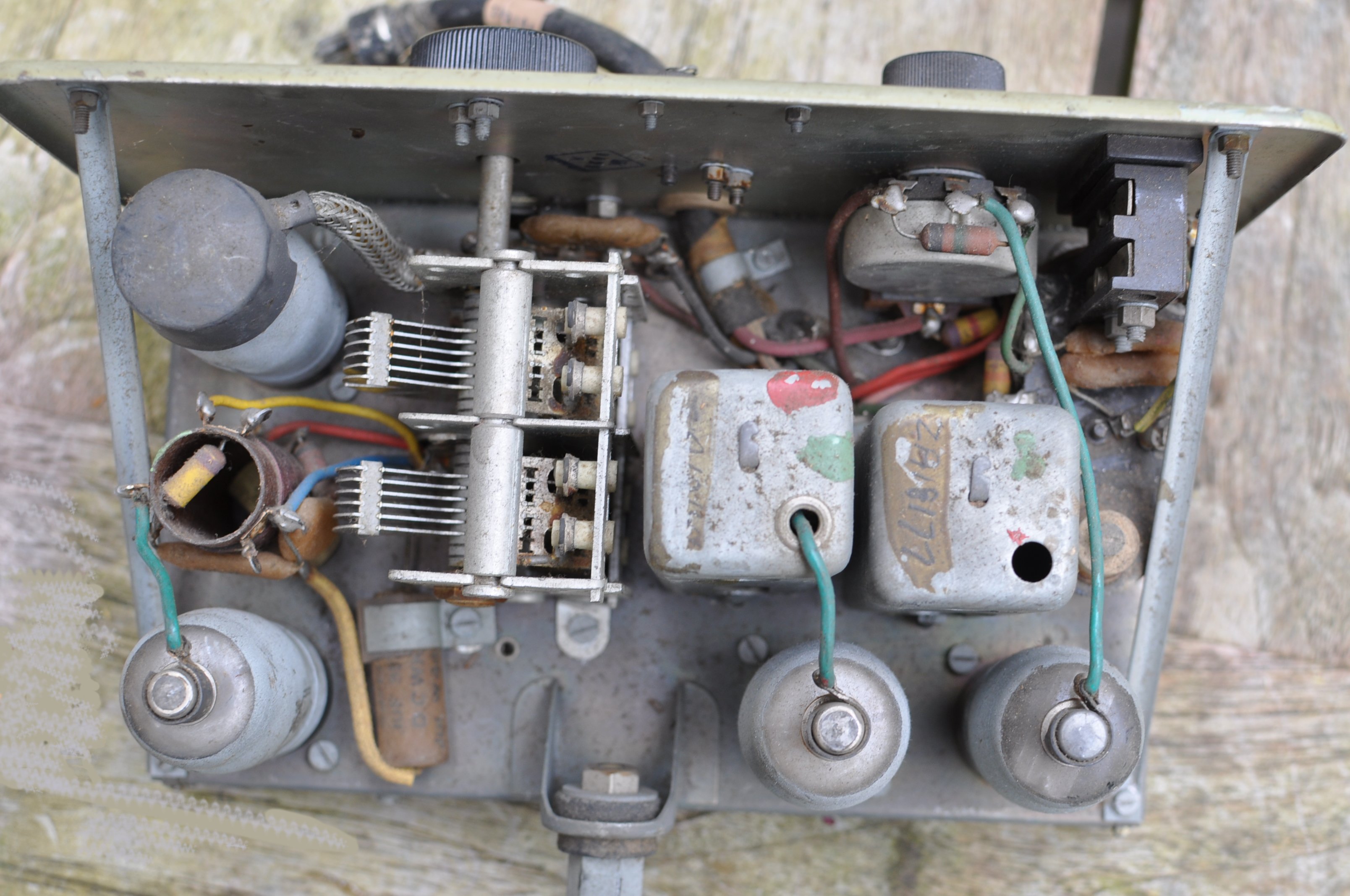
I replaced the rusty nuts and bolts by brass.

Before going any further, I decided to build a PSU that could supply, just like the battery, all three voltages: 2 V, 12 V, 162 V.

   
Receiver, back view. Looks complete.
   
Receiver, top view

The receiver gave little audio. After a long time of puzzling due to different voltage readings than were in the manual, it turned out that the wire on the right hand of the potentiometer was broken. But it was still in place, one could not see the breech. Since 2012-12-05 it is receiving well again.


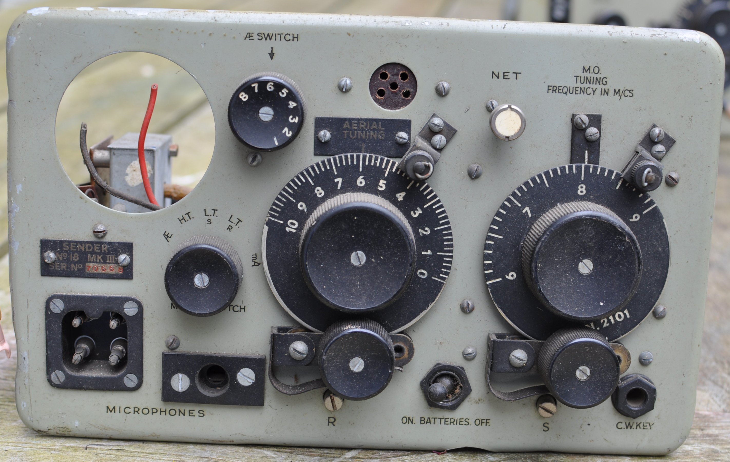
The transmitter. Marked: "SENDER No. 18 MK III SER. No. 70668"

There seems to be a hole where none should be.....

Luckily the previous owner has not altered the set, did not drill holes for other plugs and alike.


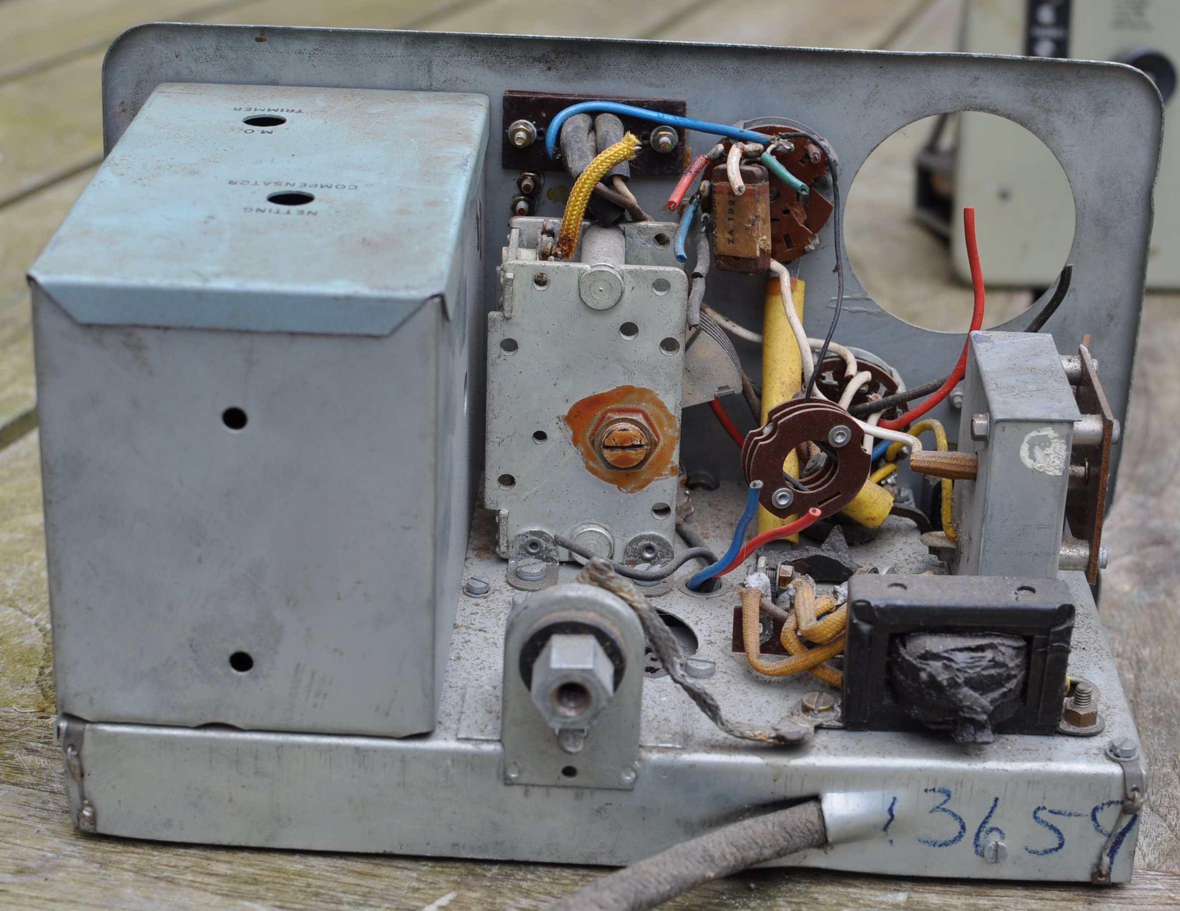
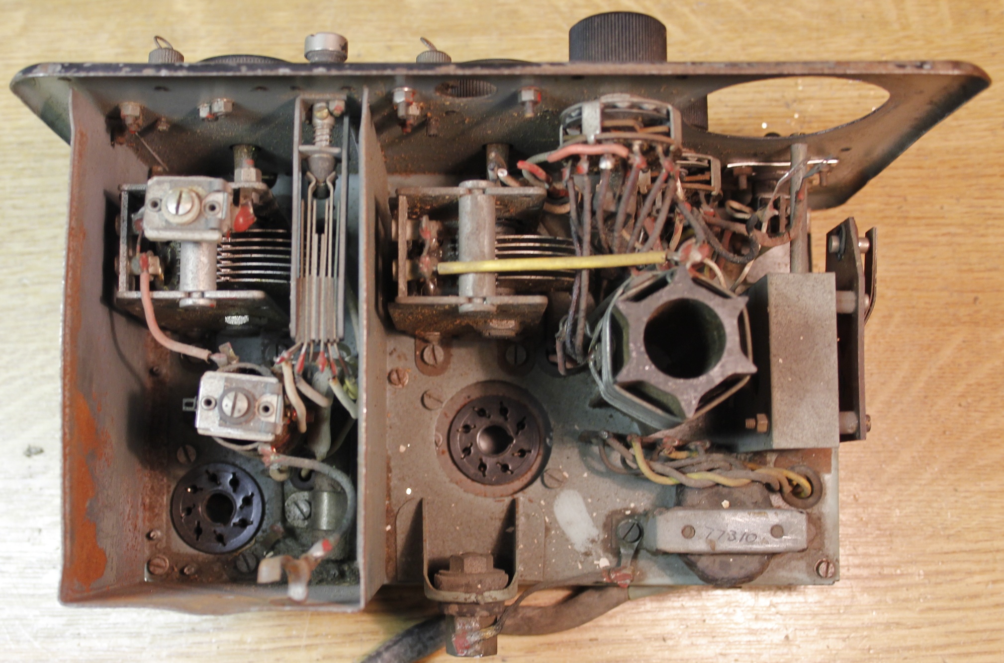
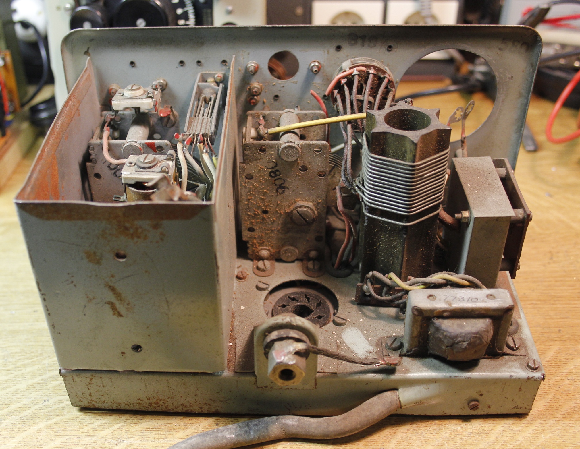
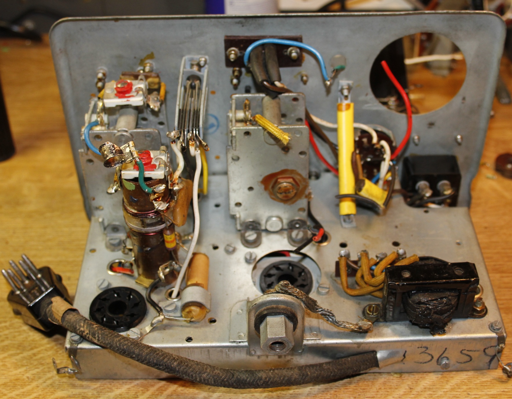
The transmitter, back view

- Meter gone,
- Tank coil gone,
- Wires cut,
- Tubes missing,
- Antenna switch is partly broken,
- Paxolin sheet that holds the antenna spring, is broken

To fix or not to fix, that is the question.


The transmitter, top view
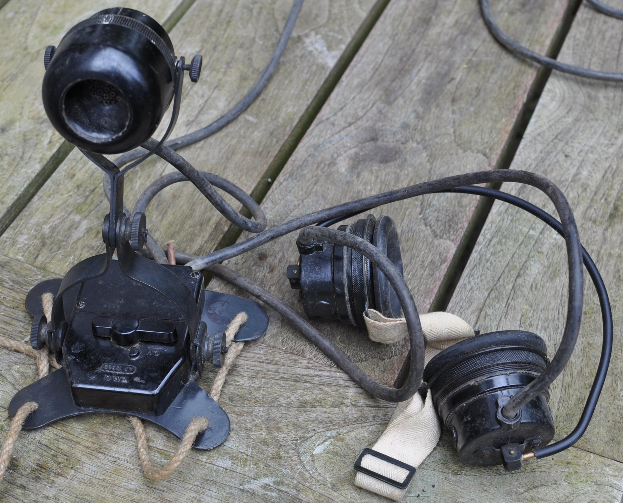


The Head gear.

A chest microphone with Send/Receive switch and a set of headphones that can be worn under a steel helmet.

   
A few days later I put an add on a well-known Dutch trading website, asking for a cabinet, to complete the sender and receiver. After a while, I got a message from a Belgian HAM, offering me a cabinet. In fact he was willing to sell me all the WS18 stuff he had, because he was not going to finish his restore plans. I drove down to his town and half a Sunday later I had 2 cabinets, 3 senders WS18 Mk.III, 2 receivers WS18 Mk.III, 1 receiver WS48, a number of spare tubes, a dozen antenna rods, a microphone and a set of headphones. And some various. In a crate on the attic I found Morse-keys, microphones and headphones. What is missing are a few of those typical microphone plugs and sockets. Anybody....?
   
Restoring the "SENDER No. 18 MK III SER. No. 70668" 2012-12-05
In the Belgian collection was a black WS18-Mk.III, serial no. 18012. It is in a bad shape and also not complete.
I decided to take parts from that sender to restore serial no.
70668 (above)
This is how it looks like. An interesting model. Look at the enlarged photos to enjoy the details like the name tags. Because the black crinkle paint, they could not print text but had to use tags.

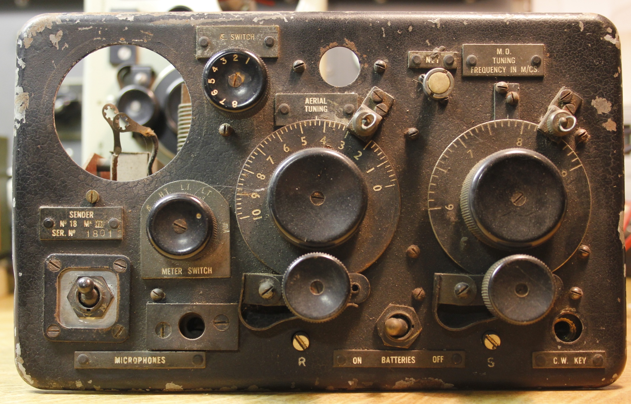
You might have observed that the microphone plug was replaced by a send/receive switch.

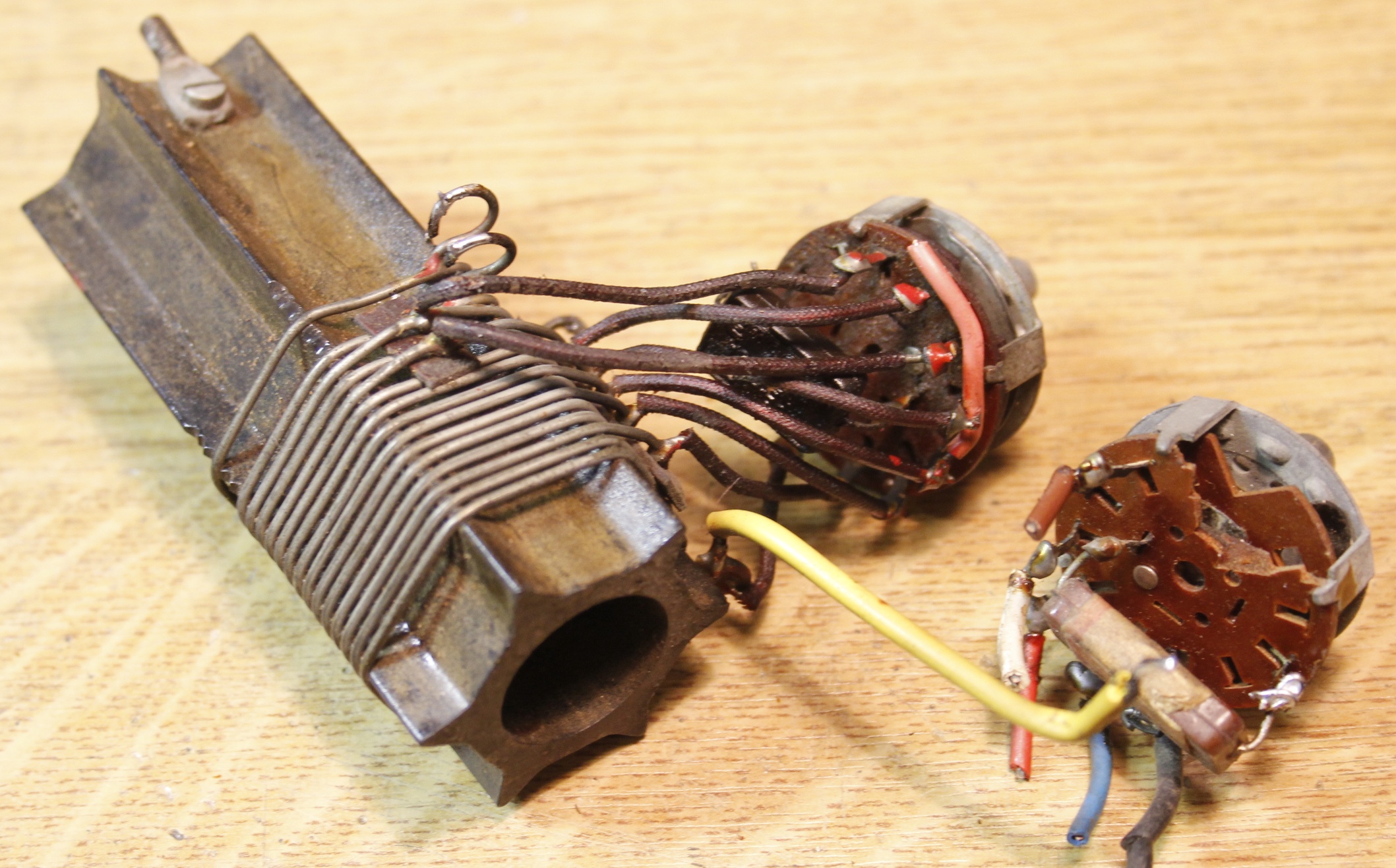
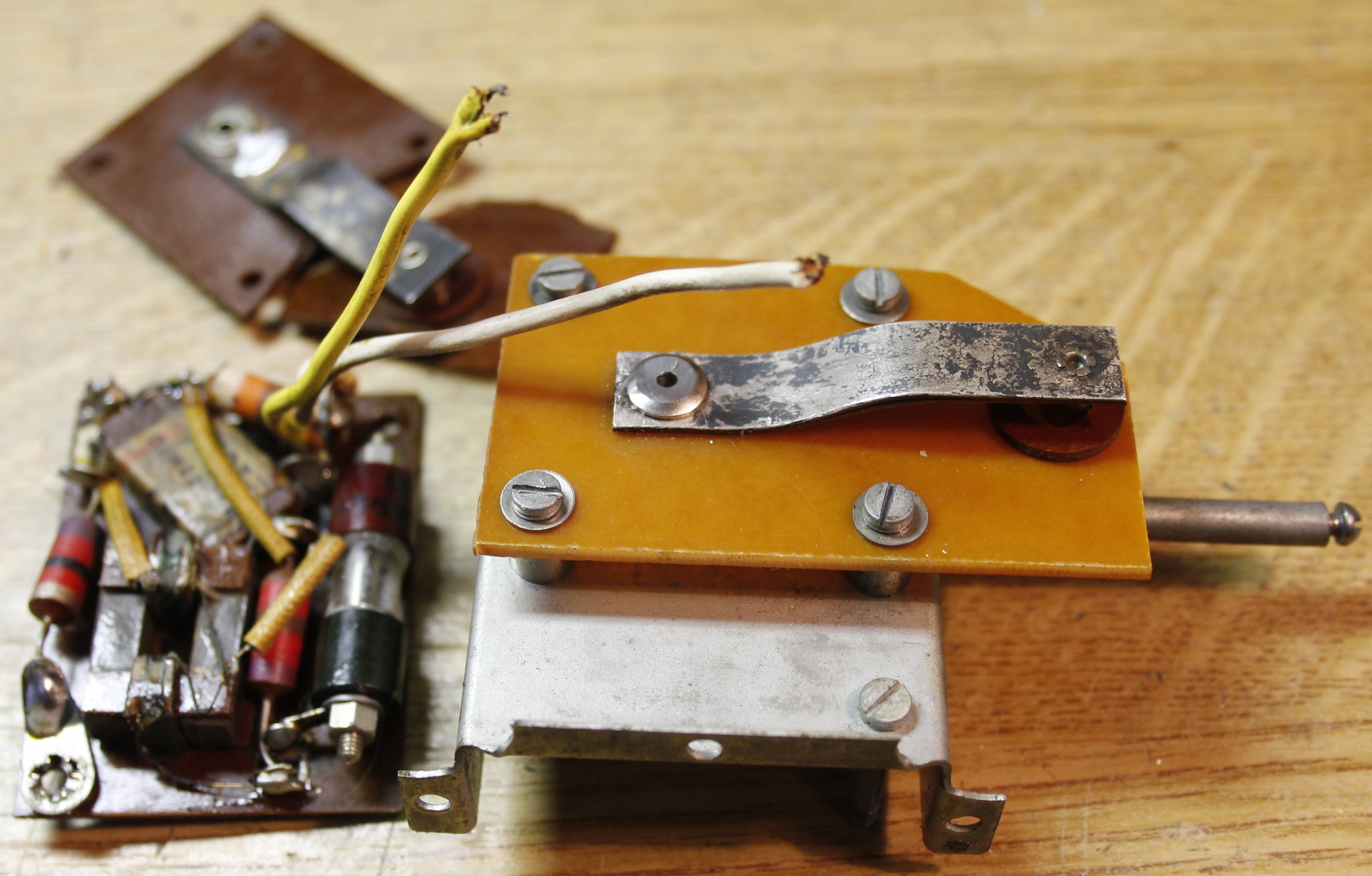
I will take out the antenna switch and tank coil and the antenna current transformer assembly.

When the antenna coil is out of the box, I will measure it, so I will be able to recreate it, if it ever comes to restoring this unit. I have a same coil former and a suitable switch will turn up from the junk box.

The future will tell what will happen to this sender...

   
I took the antena current transformer and the tank coil / antenna switch combination from the black WS18.

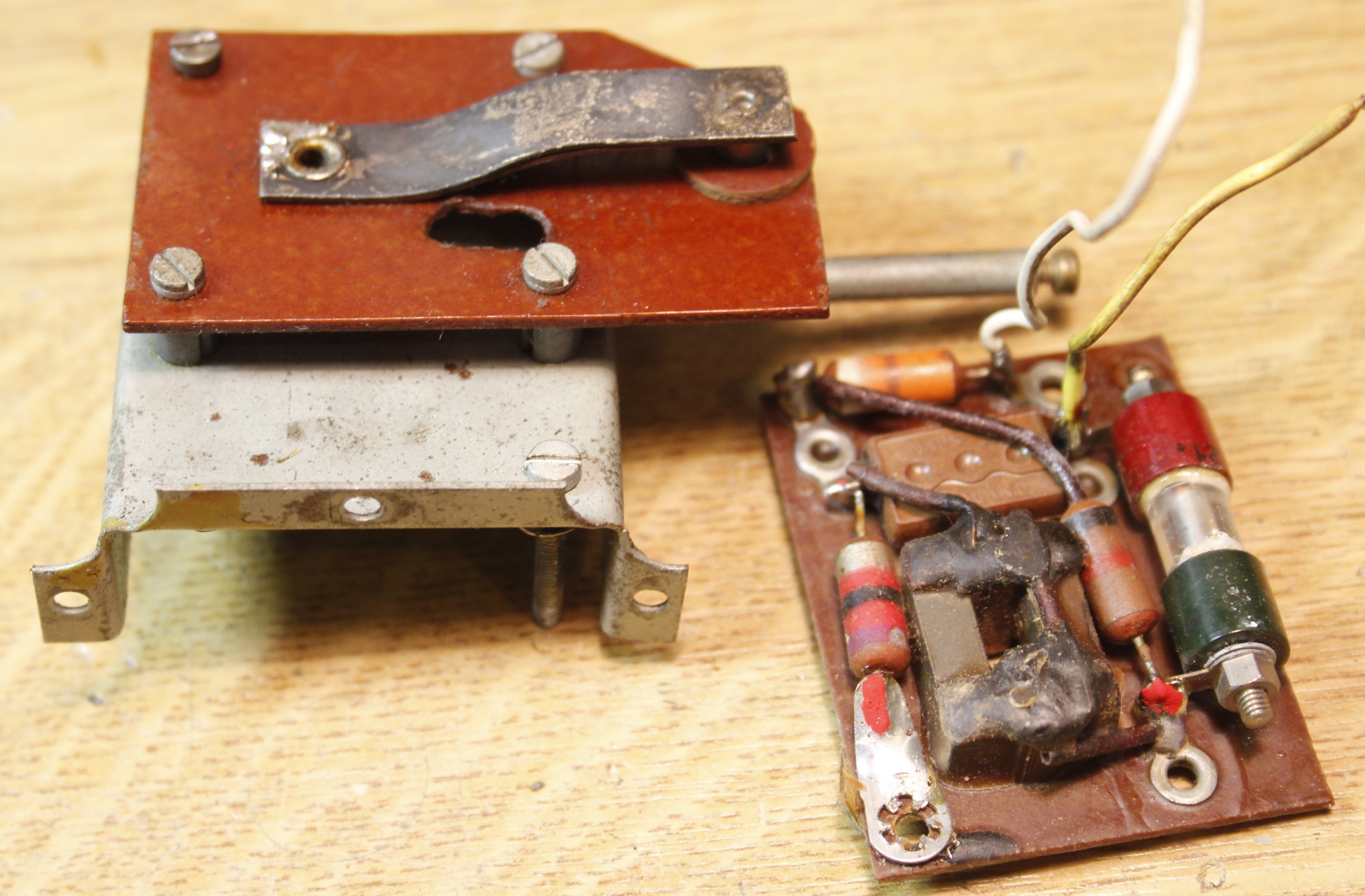
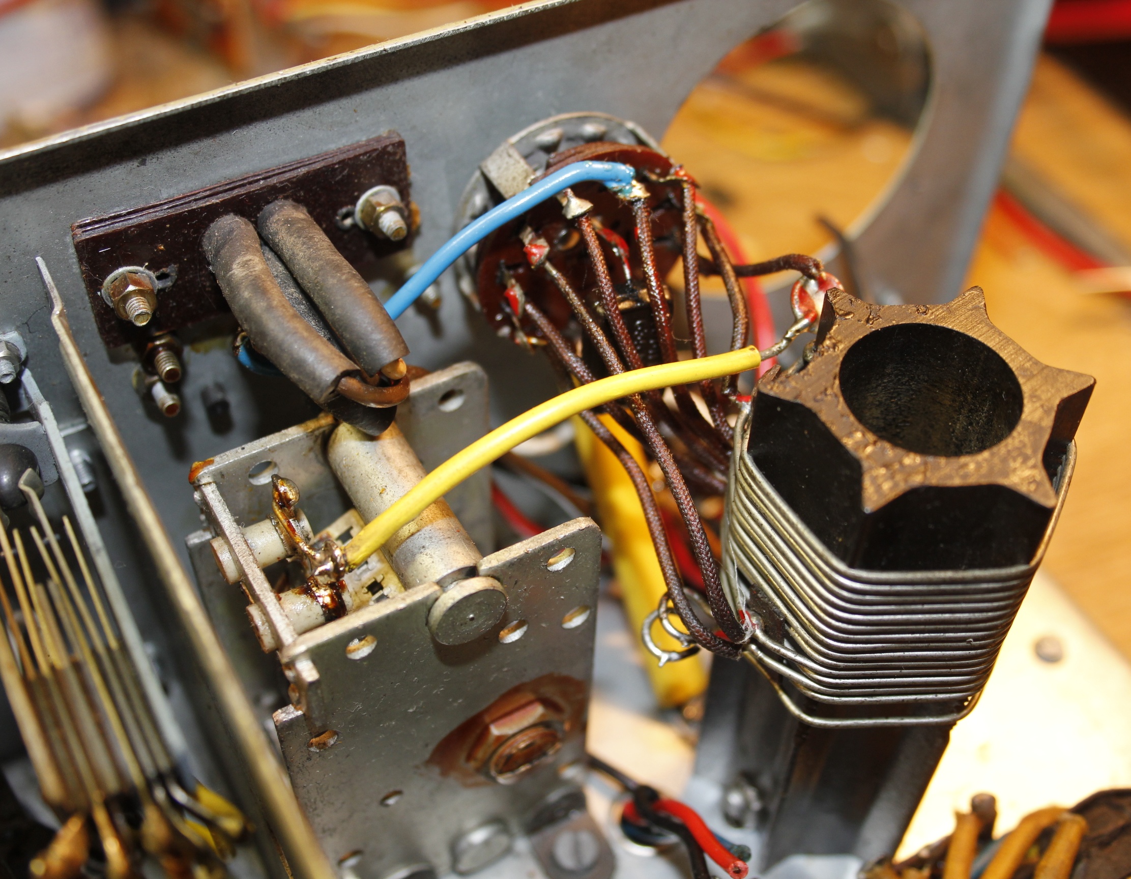
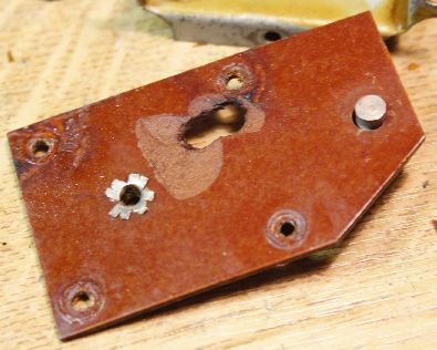
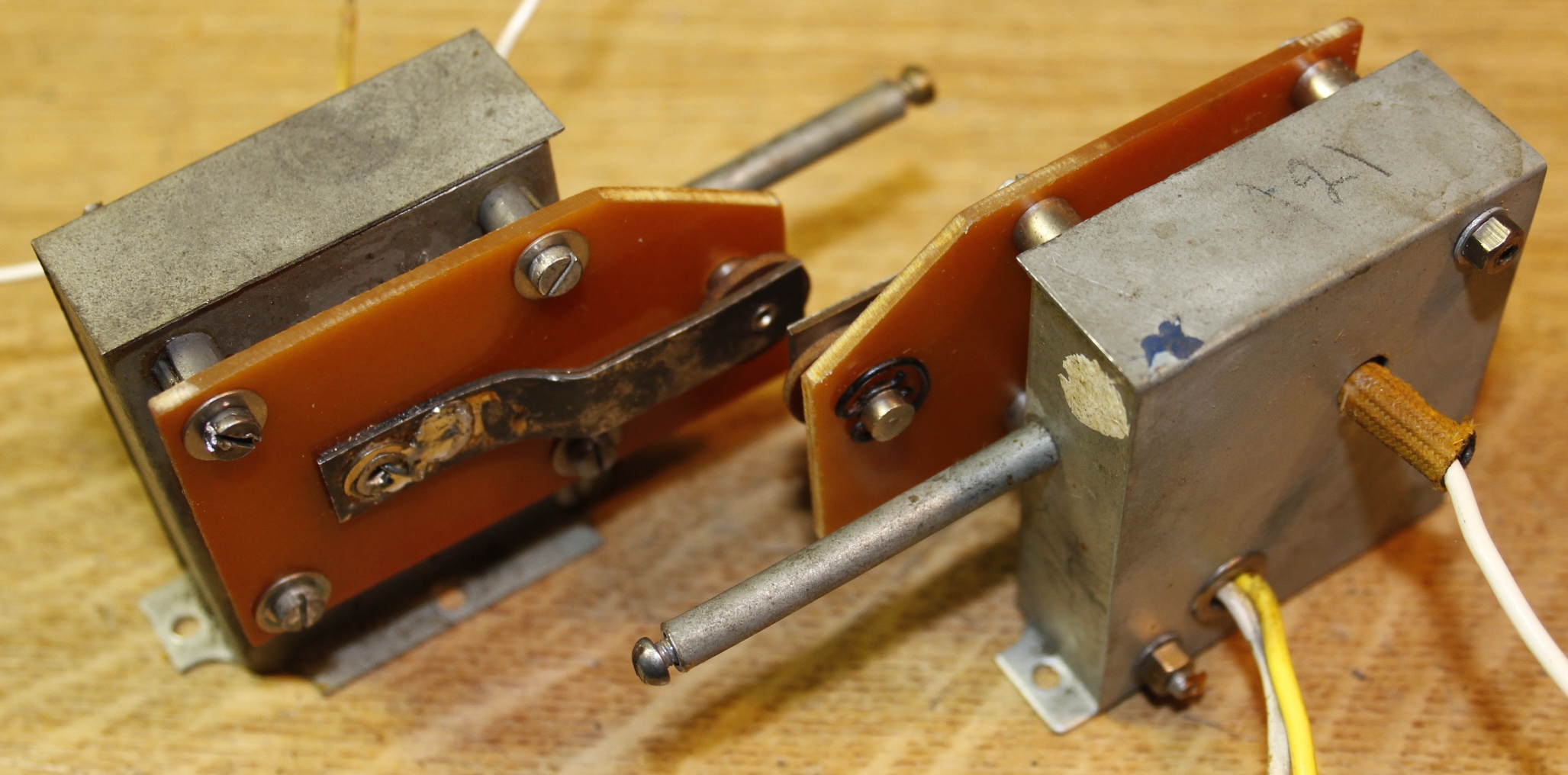
The phenolic isolator seemed ok, but turned out to have a hole in it. I decided to replace this part on both transformers, as I could take measures from this part.

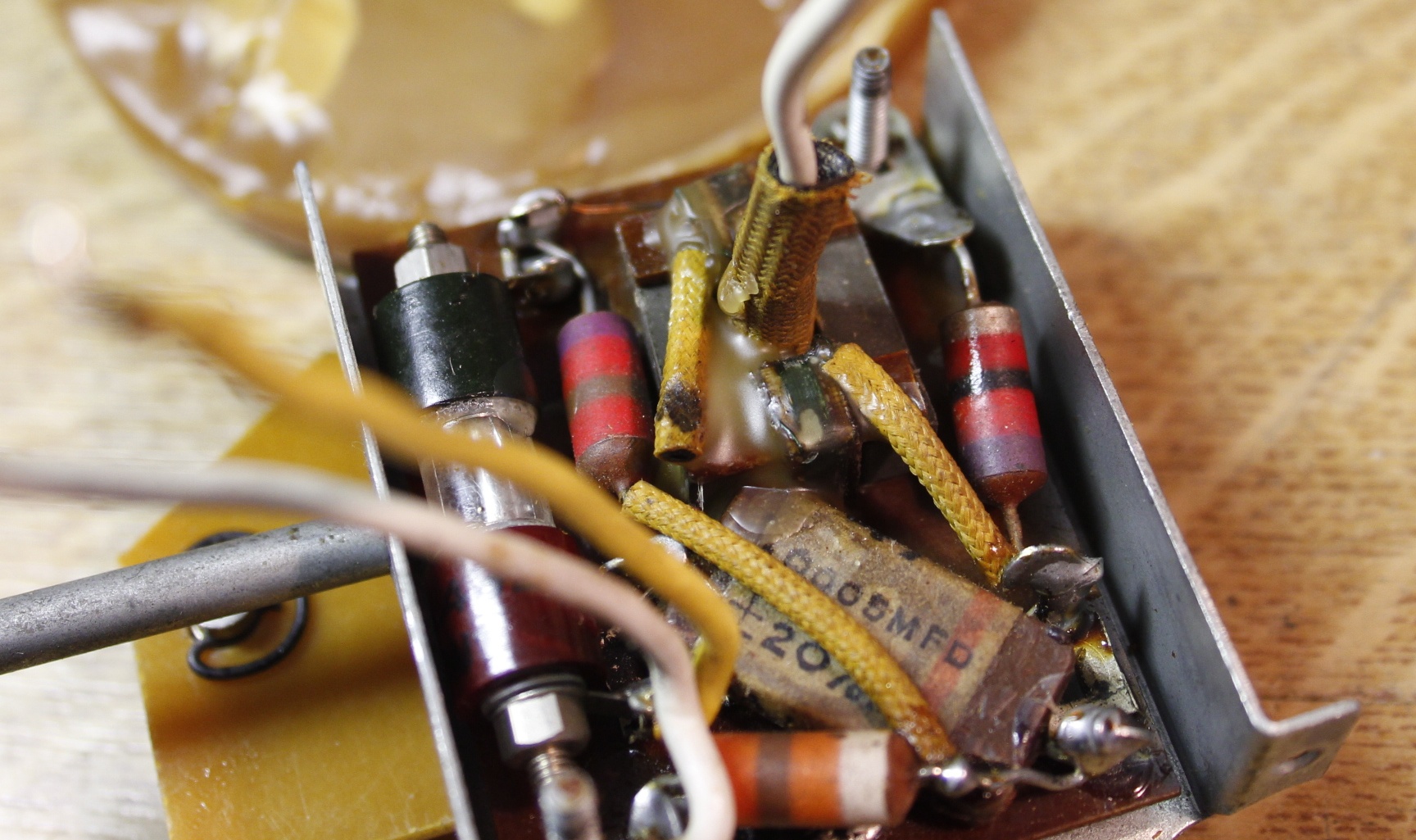
On the photo you see the interior. The part on the right side is a diode. The part in the middle a transformer core.

   
This is the tank coil / antenna switch combination. It was doable to take it out in one piece. Bottom-right shows the old, broken antenna switch.

I have more detailed photos on the coil, here, if you like.

   
The insulator sheet has a nasty hole. It looks like burnt. From this I can take measures and make a new one.

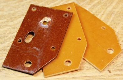
Having some suitable material, I decided to make 2 in order to fix both antenna current transformers.

   
Now, this was probably the easiest part of the restoration. The bandsaw did the work.
   
The rivet is one, used in leather repair. The head is flattened with the help of a Dremel Motor Tool ® and a sanding disk. Than a hole was drilled for the wire that connect antenna and tank coil.

This wire runs through the square core, thus induction is generated in the coil, fed through the diode to the meter.

Look at the diagram if you want to know how it works.

   
Assembled, again. The white wire goes through the core. Some extra wax was applied to protect and secure the delicate windings on the core.
   
At the end I have two restored transformers. Sender 70668 gets his own transformer back and Blacky's transformer is kept spare.
   
In order to be able to clean the set, I removed the Master Oscillator shielding. This action also grants a good look at the interior.

What needs to be done is the following:
- fit the tank coil / antenna switch,
- reconnect wiring
- replace the dried up rubber power cable,
- find a proper metering instrument,
- fire it up en see what happens.

   
The wiring in this set is mainly made of solid wire and plastic insulation. The power cable is made of flexible (litze) wire covered in rubber. This rubber is dried up and breaks off if touched.

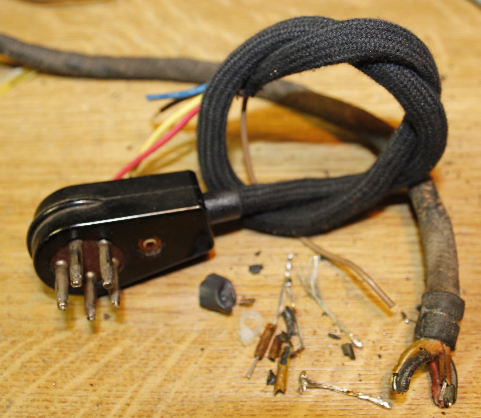
I decided to make a new cable, using the "shoe lace technique" I used before. Follow this link to see how I made this nice cable.

This is what a "new" cable can look like.

   
Bottom view. All original. Bottom-left, you see a selenium cell. This rectifier is part of the antenna current measuring circuit.

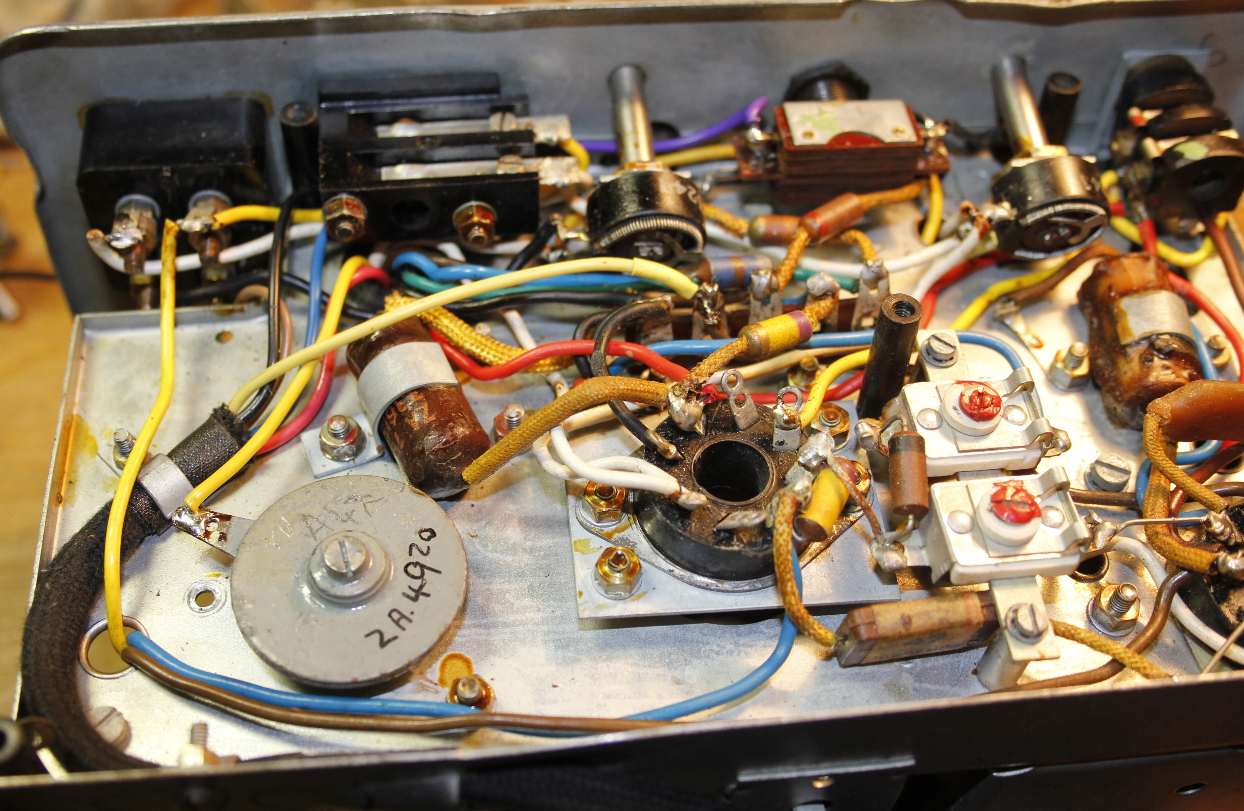
The new power cable is in place.

   
The tank coil / antenna switch are in place, wires reconnected. Too short wires were replaced.

Due to the compactness if this little rig, it is difficult to work in. The soldering iron touches other wires easy so one has to operate with caution. And is always one hand short.

No, I could not take off the front. Bolts are covered with lacquer and the first I tried was impossible to open. Slots on these bolt heads are shallow and easily damaged. I will leave them alone.

   
View on the left side. Some wires still have to be connected.
   
   
..... to be continued ......