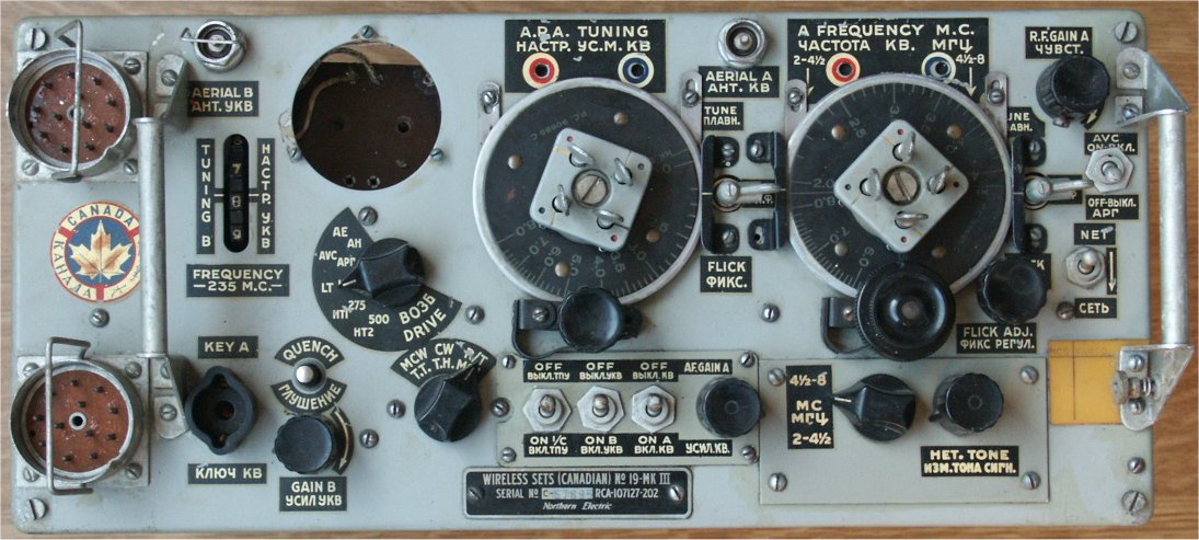
Wireless Set No. 19 Mk III Canadian - the Italian Job

This page will not be ready for a long time as the set it is committed to, is still in the restoration phase. 

This unit was in a bad shape when it was obtained. It came in a wooden box, in which it was used or 
stored by the Italian Army. It is told that Italy sold these sets to Greece en they came from Greece as 
surplus to The Netherlands. So they came a long way, all the way from Northern Electric in Montreal - Canada.

In the box a vehicle mounting was placed on which the set was mounted. In the box I obtained, were:
Wireless Sets (Canadian) no.19-Mk.III, Wireless Sets (Canadian) # 19-Mk.III Supply Unit No. 2
variometer #, controlbox # , two headsets #.

Later I succeeded in obtaining: Case, spare parts, No. C1, Case, spare valves, no. C1

Information on Plug 5 Point No. 5  ZA 1853

Nice to see are these black & white photographs, taken in an RCA factory were mainly women were constructing these sets.

The tranceiver-part

back to top
Click on the picture if you want a better view All these sets seem to have been "demilitarized", a euphemism for "brutally demolished". The Volt meter was taken out and the interior got a few blows with a hammer. Strangely, the little bolds for the meter were put back in their holes.

Click on the picture if you want a better view.

 
Here you can see the painful hole. I wonder what they did with all these meters, it must have been hundreds of them.

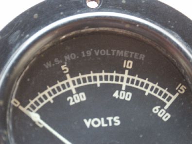
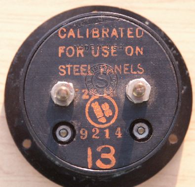
It is not an instrument of great precision or value so why remove it?

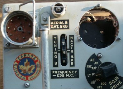
The "Canada" sticker has kept well, I am glad of that.

In the meantime I obtained an original meter, as can seen below.


The damage is not vital. Left to right:
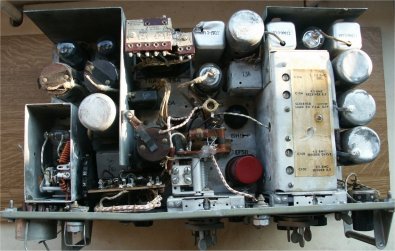
- the cover of the B-set tuner is missing
- transformer top in the middle is broken
- the hf transformer next to the transformer had a hit, even a hole
- mounting strut on the left hand varco is broken 
- right hand varco housing is dented
- the front is bended
   
  26-06-2006. Thanks to Dirk Goos, PE1FGG, The B-set-tuner is covered, again.
 
The damaged parts are well visible. Temporary repair has been made by using hot glue to stabilize the broken parts.

The set works well, in spite of the demolishing. 

 
Click on the picture if you want a better view. Bottom view. Nothing damaged, here. The bottom cover is missing. The bolts are put back in place, though. 

Click on the picture if you want a better view.


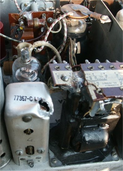
Supply unit No. 2 Mk. III

back to top
Click here if you want to see the pocket watch. This power supply unit (PSU) is in very bad shape. It is very corroded, wiring is dried up and leaking condensers did the rest. The outside is also in a bad shape.

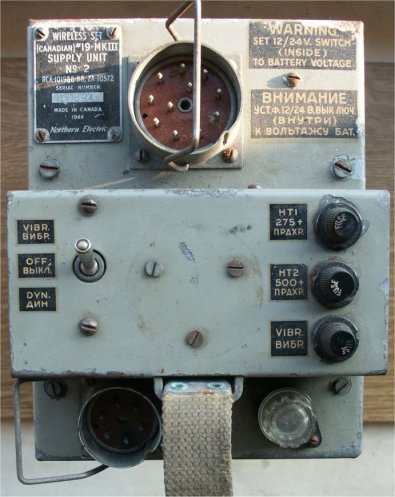
This unit utilizes a single rotating generator (dynamotor) for both high tension voltages: 275 and 500 Volts. 

It also incorporates a vibrator driven supply system in case of single use of the receiver.

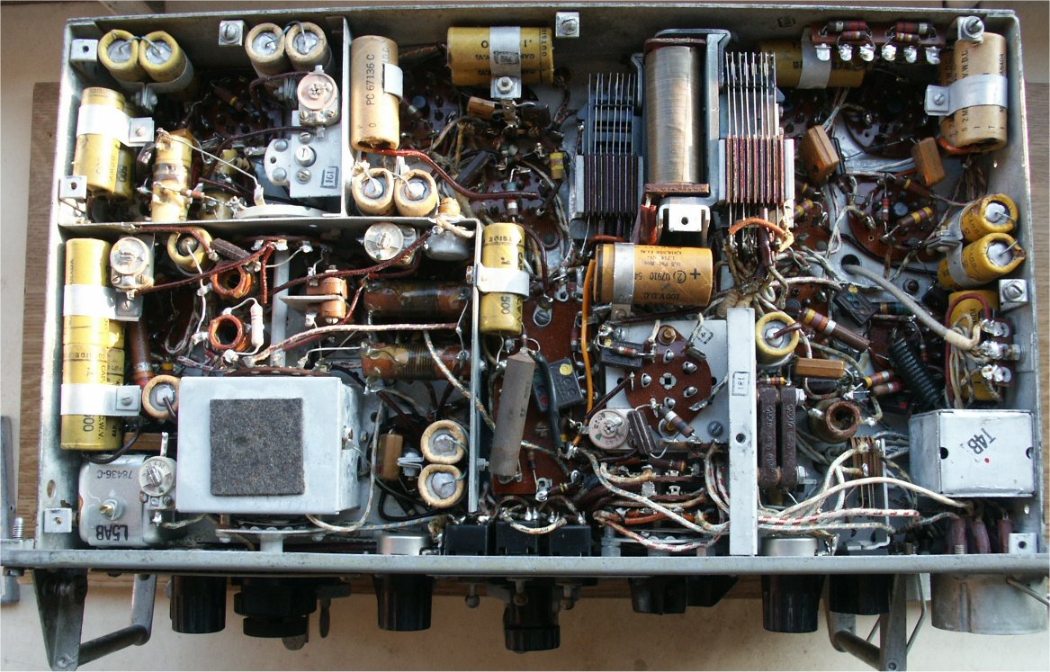
In the middle, three bolds are seen as well as an imprint of a circular shape. Originally, a plastic mounting ring for a pocket watch was fitted here.

These watches were supplied to the operators so the time could be noted. In those days wrist watches were probably not commonly worn. I have such a watch, only the rings are missing, on both my 19 sets.

 
Corrosion as result of leaking capacitors is obvious. 

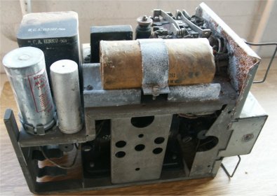
The vibrator is located at the back (left side in the picture).

Under it, an empty spare holder is present.

 
A view at the engine-room.

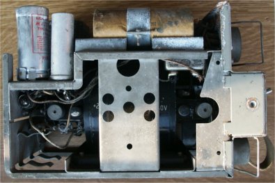
A single rotary transformer (dynamotor) supplies both voltages: 275 and 500 Volts.

My other 19 set uses a supply unit no 1 Mk. III. In this, two smaller dynamotors are used, for both voltages, one. It lacks the energy saving vibrator. That one is in working condition, however.


The Variometer attachment

back to top
photo not available, yet The Variometer is used to electrically adjust the fixed length antenna to the frequency, the set is tuned to.

It is attached to the PSU-housing by a mounting plate.

 
A simple, yet effective holder for an antenna rod is supplied and directly connected to the input terminal of the variometer.

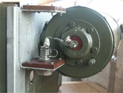
In stead of the rod assembly a long wire antenna can be connected her as well, by means of the thumb screw.

At the right side of the variometer housing the output connector can be seen.

 
The nametag is partly gone.


Back to top
Back to WS19 Index Page